Source Document
Patent No. 138912, 1880.
Extract
The propeller. In order to make it easier to handle the large 20-digit machines, a mechanism was invented which would automatically move the carriage a step at a time each time the crank was turned in the direction opposite to the normal.
The carriage moves to the right if the clutch button is in the Addition position and to the left if it is set on Subtraction.
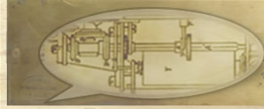
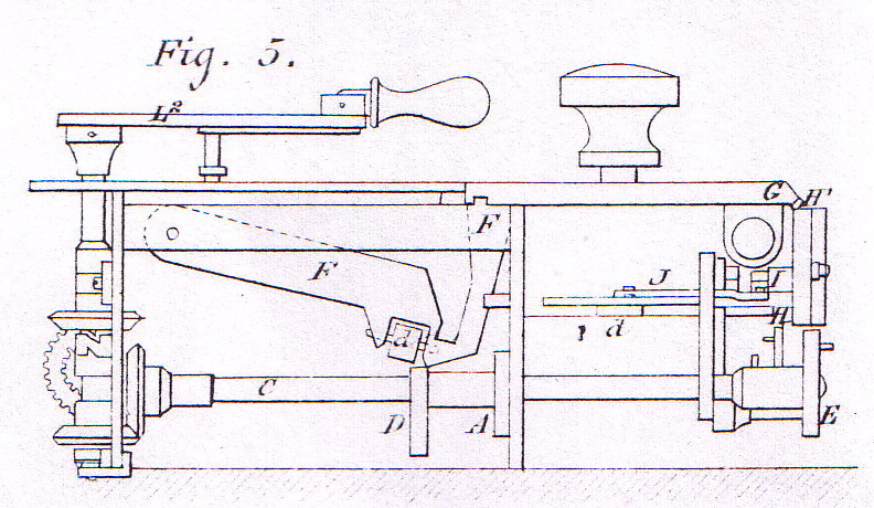
The vertical axle f (Fig 5), of the crank is mounted in two collars which allow it to move slightly up or down and it turns in two brass pipes one or other of which, by means of a suitable clutch, it can drive with it alternatively depending on the direction in which it's turning.
The upper one of these pipes carries the pinion which drives the transmission shaft; it is only driven when the crank turns in the normal direction.
The lower pipe carries a similar pinion, the opposite way around, which drives the carriage movement; it is only driven when the crank is turned in the direction opposite to normal.
The clutch which produces this result consists of a small steel ring fixed to the axle between the two pipes. This ring has two notches on opposite sides with which two studs of similar shape, jutting out from the edges of the pipes, can engage. As a result, if the crank is turned in the normal direction, the axle is held slightly up and the stud on the upper pipe engages with the notched ring and is driven by it.
But if the crank is turned in the opposite direction, the upper notch, acting on the part of the stud that forms an inclined plane, pushes the axle down slightly so that the lower stud engages with the lower notch and the lower pipe is then driven.
If the crank is then turned again in the normal direction, the inclined plane on the lower stud causes the axle to be raised and the upper stud and notch to be meshed.
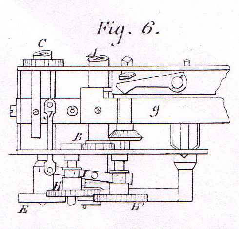
This system led to the removal of the ratchet wheel mounted on the driveshaft of ordinary machines. But, to prevent the stepped tooth cylinders possibly turning in the wrong direction, a new ratchet wheel B (fig 6) was placed on the axle of the first stepped tooth cylinder against the rear plate of the frame.
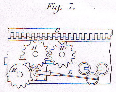
When the lower pinion turns, it drives, via a second similar pinion, a horizontal axle C (fig 5) on which is mounted an eccentric D (fig 5), a ratchet wheel A and a wheel E (fig 5, 6 & 7) with eight teeth covering half of its circumference.
The eccentric D, turning against a runner d (fig 5) which facilitates the rotation, raises a lever F whose curved end reaches under the edge of the mobile carriage plate and lifts it sufficiently to disengage the teeth of the dial wheels.
In this tipping movement of the plate, a rack G (fig 5 & 7), fixed obliquely against the lower face of the plate, engages with either a gear-wheel H or with a similar gear-wheel H' depending on whether the machine is set to addition or subtraction.
These two wheels are mounted on pipes which can slide backwards and forwards on the axles which support them.
A Lever I (Fig 6) has two studs which engage with the grooves in the pipes; it pivots about a central axle in such a way as to push simultaneously one of the wheels forward and the other back.
This lever is moved by an articulated rod mounted on the clutch bar.
Finally, the gear E is placed in such a way as to be permanently engaged with the teeth of the gear-wheel H because, when this wheel makes a complete turn, its movement along its axis, caused by the action of the lever I, is less than its thickness.
Thus, when the crank turns in the direction opposite to the normal, the gear-wheel F makes a complete turn; it drives the eight-toothed gear-wheel H and, in the opposite direction, the eight-toothed gear-wheel H'…
According to whether the machine is set for addition or subtraction, the rack G advances by eight teeth towards the right or towards the left and the size of the teeth is calculated to correspond exactly to the space between two adjacent dials on the mobile carriage.
The mobile carriage then advances one notch in the appropriate direction with each backward turn of the crank and, at the end of each turn, as a result of the effect of the eccentric D which stops raising the lever E, the carriage falls back into place and the stud automatically engages with one of the grooves of the intermediate plate of the frame. Furthermore, the edges of these grooves are chamfered to ease the entry of the studs.
A runner K (Fig 7), mounted on a clevis at the end of a steel spring L, presses on the teeth of the wheel H to prevent it overrunning the position to which it is driven by the wheel E. |

