 |
 |
 |
 |
 |
 |
|||||||
 |
 |
 |
 |
 |
 |
|||||||
1865 Patent
|
|||||||||||||||||||||||||||||||||||||||
1865 Patent |
|||||||||||||||||||||||||||||||||||||||
| «« Back to Patents |
|
|
|||||||||||||||
|
||||||||||||||||||||||
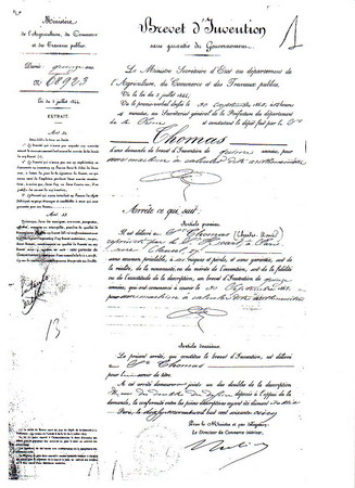
* Traduction by Cris Stenella, Belgium Patent n° 68923
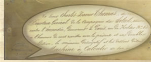
To M. Thomas, for a calculating machine, said arithmometer,
This machine, by which one can easily, quickly and correctly effect all four arithmetical operations, is the perfection of the one the inventor presented December 28th 1850. In 1818 the inventor began the trials of this invention. It is the first calculating machine invented by means of which one can operate on more figures collectively. The following description covers the entire machine, even though certain parts are already published and thus not subject to a new patent. The whole of the changes is the subject of the present patent. The present description only treats a machine with twelve positions; they are being made in sixteen and twenty positions, with quotient eraser, which machines do not need to be described, because of the principles being the same. He who constructs a machine of twelve positions can also construct one of sixteen and twenty positions, and more: it suffises to adapt the housing for receiving the mechanism, all mechanical parts being the same.
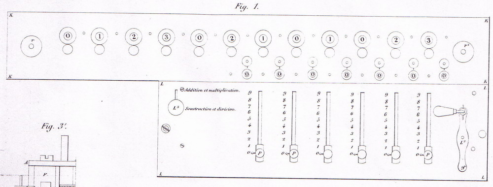
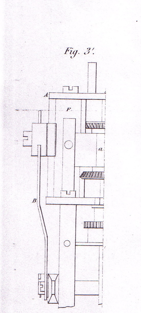
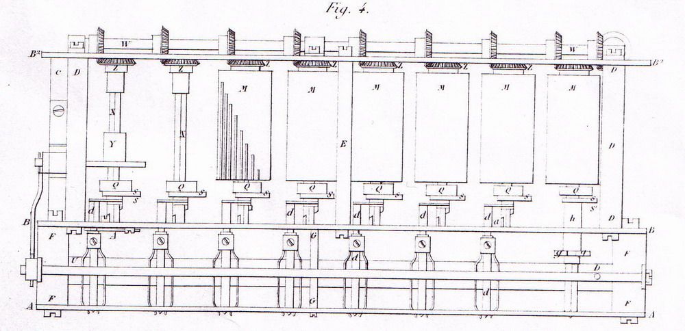
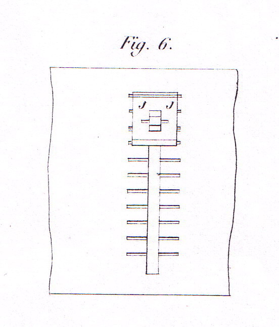
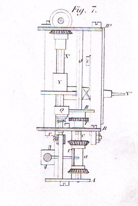
Cage The mechanism for the multiplier and the multiplicand, or, in reverse operation, divisor and quotient, is contained in a cage of 28 centimeters long by 11 centimeters wide and a height of 5 cm. This cage is composed of three plates A, B, B'' (fig. 3, 4 and 7); the two plates B and B'' are connected by : 1° two square pillars C (fig. 3); The plate A (fig 3, 4 and 5), is connected to plate B by two large round pillars F (fig. 4), and by a small round pillar G (fig. 4). On the plate A are fixed two pieces H (fig. 3), in which glides a round steel rod passing through the three pieces I (fig 2). The movement of this rod is limited by a screw in the piece I''; the rod serves as a hinge for the dial plate K (fig. 2), and allows its movement over the length of the cage, to be able to change the place of the line of dials, and to render them successively independent. The cage is covered, apart from the dial plate indicated before, by another plate with so called sliders, on which are placed the indicator buttons P (fig. 1), which slide in a groove and indicate the numbers with which one wishes to operate. Under this latter plate, of which we see a part represented in fig. 6, are cut out notches transversing the groove, serving to stop spring J at each number, to avoid errors in setting the numbers; without these notches (perfection), one sets the knob too high or too low, and it is possible to set a different number than the one indicated, without noticing; with the notches, one feels the spring stop at every notch, and one operates reliably.
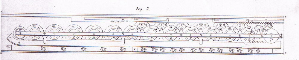
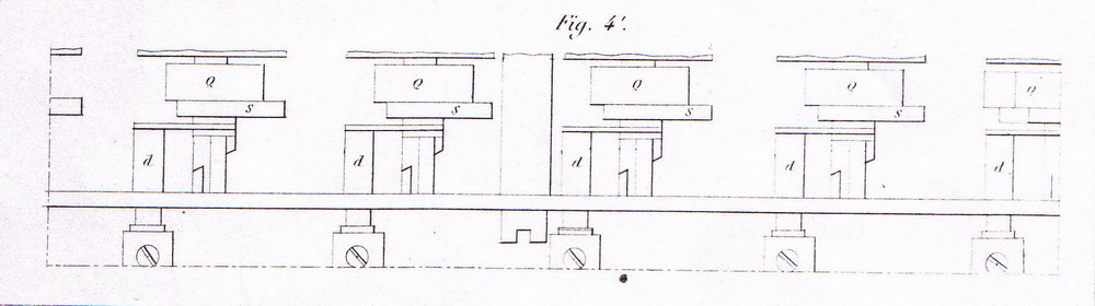
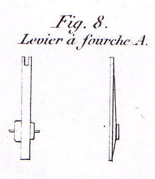
Parts mounted in the cage 1° six serrated cylinders M (fig. 4) These cylinders are cut in twenty teeth, of which eleven are removed over the entire length of the cylinder, the nine remaining ones are cut in ninths in a stairlike manner M, to represent the numbers of 1 to 9 designated on the slider plate L (fig. 1) The teeth of the cylinder mesh with a small wheel N (fig. 3); this wheel, named conductor, is cut in ten teeth and is mounted on a carrier carrying a square groove, in which enters the button P (fig. 1), which, when different numbers are set on the slider plate, makes the conductor wheel mesh with the section of the teeth of the cylinder corresponding to the number indicated by the indicator of button P. 2° on the square rod being the axle of the serrated cylinders M, is mounted on a carrier with a square hole, an iron piece Q (fig. 4), named moderating cylinder (new invention); this piece, in conjunction with the pieces R (fig. 3), moderates the acquired momentum that existed in the older machines, because the cylinder, in fast movement, would, by means of the conductor, drag along the square rod, and thus the corresponding dial, so adding, by its momentum, one or two extra teeth to the dial. With this new invention, as soon as the last tooth of the serrated cylinder ceases to mesh with the conductor N (fig. 3), the piece R, formed as a Maltese cross (invention) collides with the moderating cylinder Q (fig. 4), and thus blocks the acquired momentum, giving to the present machine an incontestable superiority in its reliability, which was missing in the old machines. On the carrier of this moderating cylinder is fixed, between the aforementioned cylinder and the carrier stop, a piece of iron, fig. 4, which at the end forms a tooth and meshes with the retainer wheel T (fig. 3). This iron piece, named retaining finger, will have its function described in a following paragraph. 3° eight square rods, going to the ends of the cage, represented by O (fig. 3), on which are mounted the following pieces: 1° on a carrier sliding on the rod, the conductor wheel N of which we have described the function above; 2° on a fixed carrier the Maltese cross, cut in ten teeth R (fig. 3), of which the function is also described higher with the moderating cylinders; 3° on the carrier of the Maltese cross is mounted a wheel with ten teeth, which we will describe in the appropriate article; 4° on a carrier a (fig. 3), called double carrier, with a reach towards both ends of the rod O and slid by means of a flat ruler U. On this double carrier are mounted two angled gears with ten teeth, which mesh with the ten-teethed angled gears v (fig. 2 and 5), mounted on the dial disks and giving the results of the operations. The double carriers mesh their gears by sliding on the rod O, either on the front or the back of the wheel v, depending on whether the operation demands that the number in the dial presents itself from 1 to 9 for addition and multiplication, or from 9 to 1 for subtraction and division. 4° Two short square rods X, X' (fig. 4). On these rods without serrated cylinder, glide, as on the rods equipped with a cylinder, a moderating cylinder with its retainer finger, for the tens and the hundreds originating from the product in multiplications and the remainder in substractions. On the last of these small square rods X' is mounted a fixed disk named stop disk. (addition to the last patent). This stop disk is, as we will describe, the object of a patent of invention and perfection, because it prevents that during the operation, the angle gears mounted on the double disk a would slide and change the direction of operation. The stop disk is made so that the change in operation can only be made when the lever L'' (fig. 1) is in its resting position. The change in operation is made by means of a lever Y'' (fig. 7); this lever is provided with an iron pin which rubs the stop disk; one can move the lever from up to down and vice versa by means of a bolt L'' (fig. 1) according to the operation which is desired, and which is indicated on the slider plate L (fig. 1). 5° At the ends of the serrated cylinders, on the other side as the moderating cylinder, is situated an angled wheel cut with 20 teeth Z (fig. 4); these wheels mesh with other angled gears also with 20 teeth, fixed on a so called transmission axle; this axle, moved by the handle L'', moves the six serrated cylinders and the two last retainer rods. These serrated cylinders are meshed with the transmission axle in such a way that the second cylinder meshes its first tooth at the moment the first cylinder meshes its second tooth, etcetera from tooth to tooth until the last one, which will mesh its first teeth when the first cylinder meshes its sixth. This way, the retainers also drop one after the other and thus avoid all error. 6° A flat ruler made out of copper, carrying seven copper pieces b (fig. 3), so called retainer triangles. 7° Seven pieces of steel, each composed of a round stalk, at the end of which is squarely connected a fork, which enters in a groove made in the disk of the moderating cylinder; this piece d (fig. 4) is named retainer fork. 8° Seven fork levers or retainer levers A (fig. 8) 9° A round steel rod, supported on one end, carrying on the support side an angled wheel with 20 teeth meshing with the transmission axle; on the other side is mounted the crank L'' (fig. 1); under the crank is, fixed on the rod, a ratchet gear, which prevents that the crank turns from right to left. This crank rod is represented in f (fig. 1 and 3). 10° A forked part g (fig. 3 and 4), which, fixed on the ruler L' by means of a screw, lifts or lowers the quotient finger (perfection). This finger S' (fig. 4) turns the wheels that count the number of revolutions of the crank and operates a series of dials which become the quotient in a division, and the multiplier in a multiplication. 11° Two parallel steel round rods i (fig. 3), which each carry a wheel of 22 mm 1/2 diameter, cut in thirty teeth, and a wheel called intermediate wheel, of 22 mm 1/2 diameter, cut in twenty teeth. The large wheel, mounted on the rod i' and close to the cage endplate B (fig. 3), meshes with the dials, fig. 2, said quotient dials; this series of dials is the counter of the number of turns of the crank, and will be the quotient, multiplier, or the number of posts in an addition.
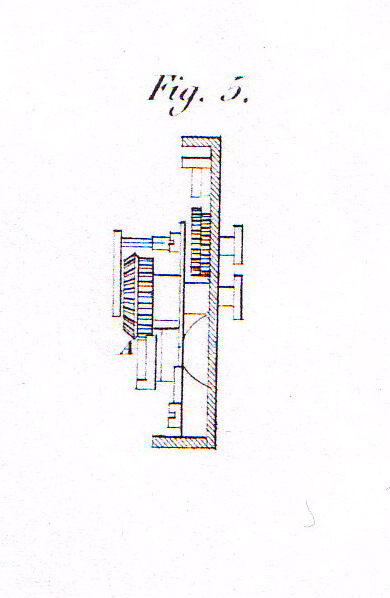
Dial plate On a plate K (fig. 1and 2), named dial plate, long 44cm, wide 6cm, and 6mm thick, are mounted twelve dial wheels m (fig. 1); each dial wheel carries ten numbers from 0 to 9, which indicate, by means of three holes drilled and milled in the plate, the obtained products. These dials are placed at 3cm distance from one another and are mounted on axles rotating between the dial plate and a rod, supported on both ends by a pillar the height of the dial wheel carriers, and forming a cage; they are stopped by leaf springs, which enter in the festoons of the dial wheels m'' (fig. 2) This dial plate can be lifted and slid along the length of the cage by means of a steel rod fixed in I, and, passing through three pieces I, slides in the pieces H (fig. 3); this rod serves as a hinge for the dial plate, and permits it to change the position of the series of dials, making them independent of the moving mechanism in the cage. Under each dial wheel and on the same carrier is a wheel cut in ten teeth, of which one has been omitted. This wheel is used, together with the large comb q (fig. 2) to return the dials to zero when the operation is finished. Touching with this wheel, and attached to the same carrier, is an angled wheel v (fig. 2), cut in ten teeth, which meshes with one of the two angled gears, equally with ten teeth, which are attached to the double carrier a (fig. 3). Each dial wheel carries a square tooth c (fig. 2), of which a corner, when passing, comes to touch the piece b (fig. 3), called retainer triangle, each time the dial turns from 0 to 9 or from 9 to 0, depending on the operation making it turn from left to right or from right to left. For the resetting to zero of the dials, the comb q (fig. 2) is put into movement by the knob r (fig. 1), which is fixed on a square axle, on which is kept by a carrier the wheel r'' (fig. 2). Said wheel set in motion raises the comb along a slanted plane, which make it mesh with the ten-toothed wheels of which one tooth has been removed, and placed on the disk of the dial wheels under the angled ten-toothed wheel V (fig. 2). The comb carries along all the dial wheels until, encountering the missing tooth of the zeroing wheel, it passes without making the dial wheel, which is on zero, turn. The comb, pushed by a strong watch spring placed at the left in the holder t (fig. 2) redescends on its own, and having redescended as much as the inclined plane allows, finds itself disconnected of the zeroing wheels, and thus permets the dials to turn for a new operation, without fear that the zeroing wheel would mesh with said comb.
Multiplier or quotient indicator and eraser. In earlier machines than the one we describe today, the rotation counter of the crank, or, differently said, the multiplier or quotient indicator, was simply a finger, which, mounted on the first cylinder, made turn a wheel cut in ten teeth and indicating the number of crank rotations, and, when the operation was finished, one was obliged to return every quotient wheel to zero manually. But to zeroise, by hand, each quotient dial of a machine of sixteen or twenty positions after a large operation, made the operator lose too much time. The machine having for goal not only the correctness, but also the swiftness of every operation, the most active research has been done to surpress this loss of time in the operation of the machine. It has thus been urgent to find a means that could permit to do for the multipliers or quotients what has already been implemented for the products or dividers, it is to say, to return all the dials to zero in one movement. For this, all the quotient or multiplier dials have been mounted on rotating axles, which are provided with a carrier, on which is, apart from the dial, a steel wheel cut in 18 teeth, of which one has been removed for zeroising. By means of a holder t'' (fig. 2), a knob r' (fig. 1) is mounted in the same way as the knob r described higher for the zeroising of the products and dividers. This knob r'' turns a wheel hidden under the holder in a cavity cut in the top plate. This wheel meshes with another wheel of comparable size, which turns on the smooth part of a carrying screw x (fig. 2). This last wheel meshes with the small comb v (fig. 2), which, like the comb q (fig. 2), rising on an inclined plane, comes to mesh with the steel wheels cut in 18 teeth s (fig. 2) until, meeting the removed tooth s (fig. 2), it passes without turning the dial, which remains at zero; then, letting go of the button, the watch spring fixed in the holder makes the comb descend, and again sliding on the inclined planes, it decouples and allows the quotient or multiplier dials to turn for another operation, without the wheels meshing with the teeth of the small comb. This addition to the old machine, which was exposed at Stettin, 1865, has yielded its inventor the honorary medal. This mechanism has made a very thick top plate necessary, because all these effects, couplings and decouplings take place in the thickness of the plate, hollowed out to this effect; it is not otherwise possible without interfering with the mechanism for the product and divider dials. Carry-over In the old machines, carry-over was effected by a double steel inclined plane, fixed to the dial, which pressed on the retainer lever and decoupled it by making it drop vertically; it could happen though, if several inclined planes of the dials pressed at the same time on the retainer levers corresponding to those dials, these levers, made hard to press down due to their number, instead of reclining, pushed the carriage upwards, and the meshing of the angled wheels and the dials, having become too weak by the rising of the carriage, produced false results in these positions. To do away with this inconvenience, we had put in communication with the serrated cylinder from the middle of the cage a steel hook, which, as soon as the crank moved, fell on the dial plate and thus prevented it from rising. This hook left the carriage as soon as the crank returned to its resting position, permitting the carriage to be lifted and slid; but to this hook system, there was a large inconvenience: if it happened that a cause for stoppage occured during the rotation of the crank, this hook, not rising until the crank was back at its starting point, made it impossible to rise the carriage, and it became quite difficult, not to say impossible, to remedy the cause of the stoppage. In the new machine, the piece with the double inclined plane has been replaced by a square tooth c (fig. 2), attached to every dial, which, when passing from 0 to 9 or from 9 to zero, touches horizontally the piece b (fig. 3) called the retainer triangle, instead of making it drop vertically, which replaces the hook, because the carriage cannot lift anymore with this new carry-over system. This retainer triangle b (fig. 3), being touched horizontally, drops the quotient finger S (fig. 4) by means of the piece A (fig. 4 and 8), named retainer lever or fork lever. This fork lever tips over by means of a pin which passes through it and is fastened in a copper block cut for the passage of the lever; this block is fixed on the cage plate by a screw e (fig. 3). This retainer or fork lever operates on the finger S by means of the stalk d (fig. 4), which receives in a groove the fork of this lever. At the end of this stalk, there is a steel fork which enters in the circular groove of the carrier of the moderating cylinder Q. (fig. 4) The round stalk d, in descending, thus makes the moderating cylinder drop, and by consequence the retaining finger S attached to it (fig. 4); This finger, in turning, meshes with one tooth of the retainer wheel T (fig. 3) mounted on the carrier of the Maltese cross; continuing to turn with its square axle, the carrier of the moderating cylinder, the end of which is filed in a spiral pattern, encounters a steel piece d (fig. 4) which then forces the moderating cylinder and the retaining finger back to their original position, making the retaining finger pass between the Maltese cross B and the retainer wheel T, until the dial wheel, passing from 0 to 9 or from 9 to 0 according to the operation, again touches the retainer triangle, thus making the retaining finger drop. This new perfection in the carry-over process is made reliable by means of double springs attached to a support. This support is kept on the stalk carrying the retainer fork d (fig. 4) by a screw. The cage plate A (fig. 4) on which we see the spring mentioned above folded into a triangle, is milled halfway from both sides at a sharp angle. In this way, when a carry-over takes place, the spring makes the retainer finger drop completely. In the same way, when rising again on the inclined plane d (fig. 4), it hardly reaches half of the way up when the spring makes it remount entirely; by means of this double spring, carry-over is very reliable, because it cannot remain halfway, but only either drop completely, or rise completely. Operating instructions The machine operates according to the basic arithmetical principles, and its movements seem to represent and follow the movements that one has to make to obtain the wanted result. Addition. One adds by inscribing with the pointed indicator buttons P (fig. 1) the numbers on which one wishes to operate, and, placing the changing lever L3 (fig. 1) on the words "addition et multiplication", one turns the crank until it returns at its starting point, and produces in the dials the numbers indicated by the buttons. Recommencing for every number as described above, one will have added the number inscribed in the second step to the first one inscribed in the product register. If there is a third number, or a fourth or more to add, one recommences by inscribing the number each time with the buttons P, and one gives the crank one turn only each time. Multiplication. One proceeds as stated above for addition, inscribing the number one wants to multiply by means of the buttons P (fig. 1); one also puts the button L3 (fig. 1) on the words "addition et multiplication", and one turns the crank until the multiplier appears in the quotient or multiplier windows. So, having to multiply 987.654 by 657.892, one inscribes on the so-called slider plate the number 987.554; then, grabbing the crank, one turns twice, the number 2 being the number of units in the multiplier; after the two turns, the number has appeared in the quotient and multiplier windows, and on the dial plate one sees appear in the product windows the number 1.975.308, which is the multiplicand multiplied by 2. Moving the dial plate one step from left to right, one puts the number 0 tens above the button 4 units, to multiply tens by units; taking the crank, one makes nine rotations, the number 9 being the number of units of tens; so the number 9 appears in the tens window of the multiplier register, and on the dial plate, one reads the number 90.864.168, which is the multiplicand multiplied by 92. Placing the carriage one more step from left to right, one multiplies with units the hundreds; one makes eight turns with the crank, 8 being the number of hundreds in the multiplier; this number 8 appears in its rank in the multiplier windows, and one reads on the dial plate the number 880.987.358 or the multiplicand multiplied by 892; moving again the carriage, one makes seven turns of the crank, the number 7 being the number of units of thousands by which one wants to multiply. The number 7 presents itself in the multiplier windows, and one reads on the dial plate the number 7.794.565.368, which is the multiplicand multiplied by 7.892; moving again the carriage with one step to the right, one gives the crank 5 turns, the number 5 being the number of units of tenthousands of the multiplier; this number having appeared in its turn in the multiplier windows, one reads on the dial plate the number 57.177.256.368, which is the multiplicand multiplied by 57.892; moving as above once more the carriage, one makes six turns of the crank, the number 6 being the number of hundred thousands by which one wants to multiply; one reads then in the multiplier windows the number 657.892, and in the product windows the number 649.769.665.368, the demanded product. The explanation to detail the operation is only as long to make the operation of the machine well understood; this multiplication takes twelve seconds on the machine. Subtraction. One places in the product dials the number of which one wishes to substract; this number being placed there, one switches the button L3 to the words "soustraction et division", then, forming the number to substract with the input sliders P, one turns the crank once, and the remainder or difference is written in the product dials. Division - The dividend is written in the product dials, which is done by opening the dial plate, and writing the number with the small buttuns which accompany each window. The divisor is written, like the multiplicand, with the indicator buttons P (fig. 1). One works in the opposite sense of multiplication, it is to say, starting from the numbers on the left. Thus, to divide 625 by 25 : put the 62 above 25, and turn the crank until the top number is smaller than the lower one; one sees the number 2 form itself in the left quotient window; on top stays the number 125; one moves the dial plate one step to the left, and thus has the number 125, with the number 25 under its rightmost numbers; turning the crank until the lower number can no longer be contained in the top number, one sees the number 25 in the quotient windows, and 0 in the dividend windows; the number 25 is contained 25 times into 625. It is unnecessary to mention that the button L3 must, before the operation, be pushed to the side indicated "soustraction et division" A more elaborate description has appeared as a brochure, and makes known all the advantages one can have from this very machine to solve all arithmetical problems.
** Traduction by Cris Stenella, Belgium ** |
© Valéry Monnier 2023 valery.monnier@gmail.com www.arithmometre.org |