 |
 |
 |
 |
 |
 |
|||||||
 |
 |
 |
 |
 |
 |
|||||||
1849 Patent (addition)
|
|||||||||||||||||||||||||||||||||||||||
1849 Patent (addition) |
|||||||||||||||||||||||||||||||||||||||
| «« Back to Patents |
|
|
|||||||||||||||
Figures |
|||||||||
Free digital document |
|
HTML document |
||||||||||
* English translation by Brian Stone, Australia 2007
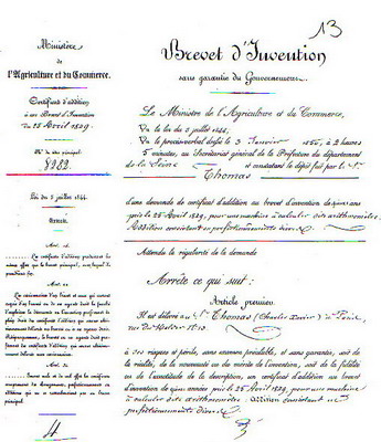
PATENT N° 8282 (Improvements) Description of various improvements
A patent was granted to Monsieur Thomas, de Colmar, for the invention of a calculating machine named Arithmometer, on the 6th of July 1849 for a duration of 15 years. The original invention on which this machine is based goes back to 1820, as attested in the patent granted to Mr Thomas on the 23rd of January 1821. Until then, despite the researches and the labours to which the most eminent men had put themselves, over a period of 200 years, it had not been possible to create any machine capable of multiplying several digits at once. Having found a solution to this problem, Mr Thomas worked diligently to perfect his calculating machine, and it was only after thirty years and many attempts that he eventually overcame the difficulty of controlling the cost price so that his machine could be put within the grasp of all classes of people and become a useful benefit to the public.
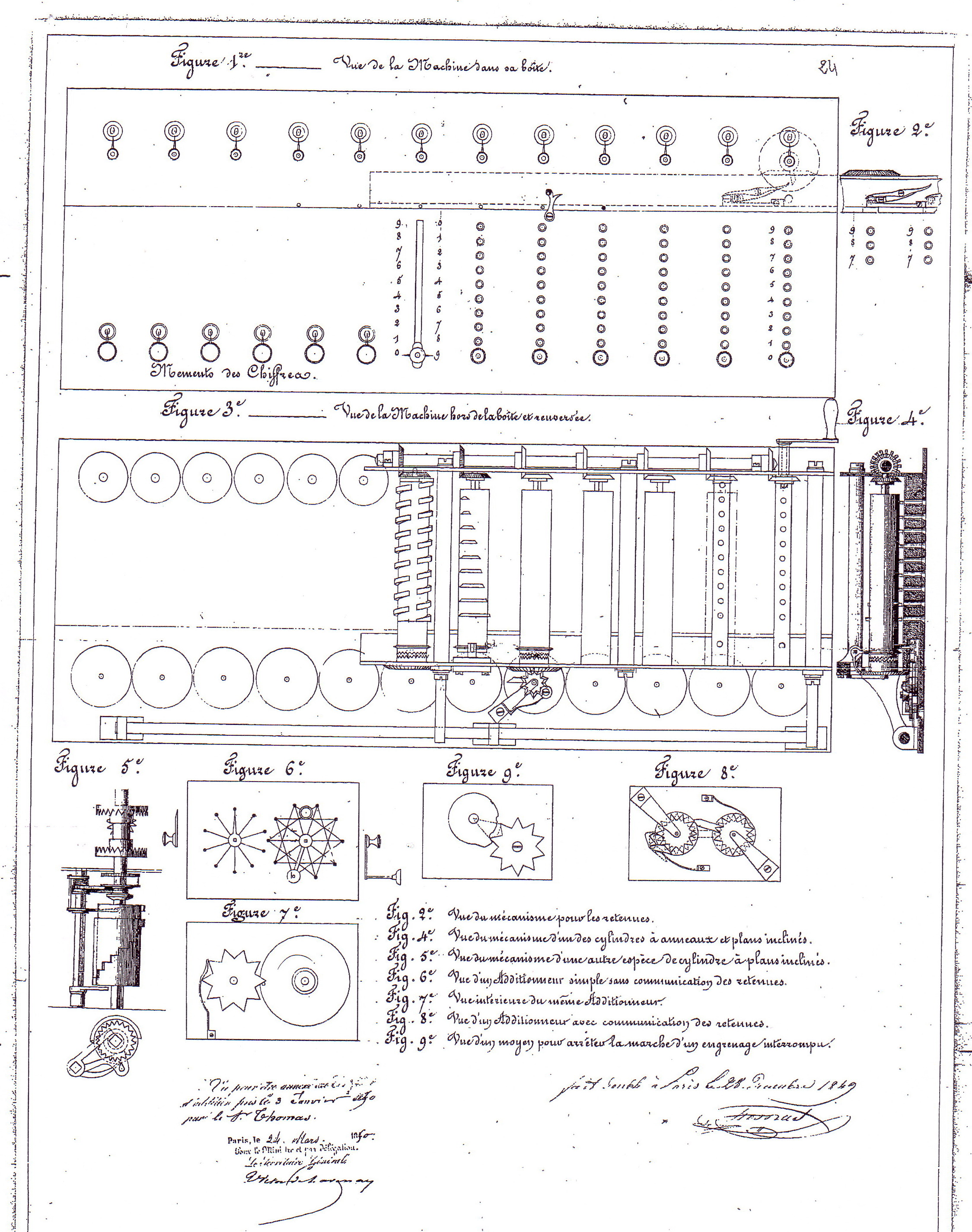
Description of the improvements In the machine patented on the 6th of July last, the mechanism consists of grooved [toothed] rolls or cylinders which transmit movement to pinions which pass it on to the dial wheels. In the perfected machine, the grooved cylinders are replaced by cylinders with circular rings [formed on them] which transmit the movement directly to the dial wheels ; thus it is no longer necessary to include the meshing pinions which required the cylinders to be toothed. This wheel causes the dial wheels to move. They are the same as in the basic machine.
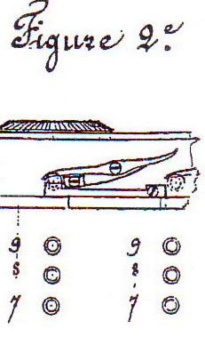
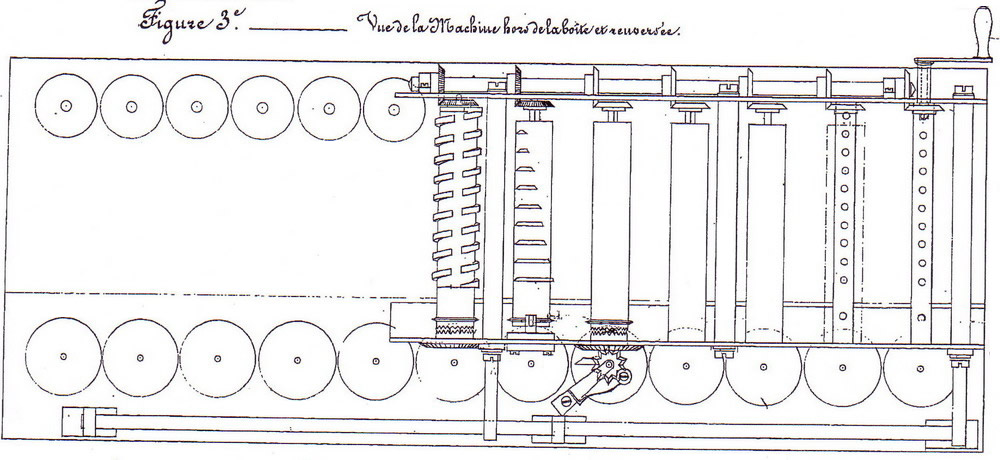
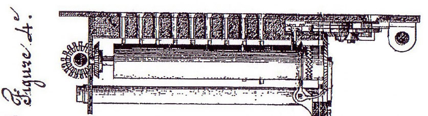
Form of the cylinders Nine ring sections are formed around, and projecting from, each cylinder, at right angles to its axis and equispaced from one another. These ring sections are of differing lengths, in the proportions 1 to 2, 2 to 3, and so on up to nine, such that the first ring corresponds to the number 1, the next to N° 2 and the ninth to number 9. At the end of the cylinder there is also a tenth ring section of the same dimension as the first, used in carrying (Figures 3 and 4).
The movement The machine has a cover plate pierced by holes facing the length of each cylinder. By introducing a peg into these holes, since each ring section begins in an inclined plane, as the cylinder turns this inclined plane bears upon the peg and causes the cylinder to advance towards the dial wheel, with which it engages, and which it forces to rotate while ever the peg remains engaged behind the ring.
Carrying Carrying is performed in the same way as in the machine with toothed cylinders, but by a method adapted to the inclined planes (Figures 1 and 2.) In order that the dial wheels, which are free at the instant of stopping, shall not move past the indicated figure due to their momentum, at the end of each cylinder a complete ring has been added which goes around the entire circumference. A small square [bellcrank? escape lever?] like those in [clockwork] bells is attached to the plate such that one of its arms can drop between two teeth of the wheel and the other can slide on the ring via a slot.
Another improvement A third variety of cylinder may be employed, having neither tooth grooves nor rings. The nine digit values are produced by solid sections and gaps ; in these cylinders the circumference is perfectly uniform ; a sheet of brass two millimeters thick is fixed over 9/20 of the circumference. When the multiplier knob is moved on to one of the nine digit values and the sylinder starts to rotate, the thickness of the brass sheet forces the lever which has been put on to one of the nine figures to rise two millimeters ; this movement engages the cylinder with the wheel which carries the movement to the dial wheels, and at the same time lifts a small lever which holds that wheel stationary.
Carrying Carrying occurs as with cylinders having rings. Beyond the ninth step position on [along?] the cylinder, there is a step positioned on the twelfth part of the cylinder. That is, on its end which is used for the carries, a lever sliding on the tenth division of the circle is pushed in the case of a carry to the twelfth division where it is lifted by that step which produces one unit, and an inclined plane machined on the cylinder returns this lever to its tenth division. For the mechanism of this type of cylinder, there is required an arbor of square section for more [of its length] than for cylinders having rings. This square arbor carries three levers needed for the movements ; the first can slide along 9/12ths of the cylinder to operate the figures from 1 to 9. A second lever is opposite the tenth division of the cylinder for the carry ; its movement is limited to between the 10th to the 12th divisions to position it out of reach of the step which produces the carry. When the spring makes the levers fall back, the grooved wheel is retracted, disengages, and returns everything to rest.
The rest of the mechanism is the same as in the other machines. The present example has been constructed with the cylinders which bear rings ; the rings are the more beneficial improvement. View the illustrations
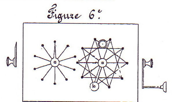
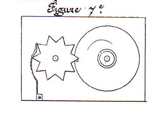
An improvement of another nature A plate 4 ½ cm by 7 ½ cm has beneath it a dial on which are marked the ten figures from 0 to 9 ; between the zero and the nine is a pin which moves by one-tenth [revolution] another dial in order to perform carrying at every turn, which is achieved by a gear wheel with ten teeth of star form ; a pawl [?] placed between [?every] two teeth stops the dial at every digit. On the plate are marked ten points ; a small handle movable by the finger from one of these points to another causes the figures to show through a small window machined in the plates. For addition, the handle is turned from left to right and for subtraction from right to left ; to operate the machine it is only necessary to turn the handle from the point where it currently is, passing over as many points as the figure has units ; if it is desired to add one to some figure, move [the handle] to the following point ; if one wishes to add nine, pass nine points. To make the operation easier, lines are marked between the points ; one line runs from every point to the third point [away] ; other lines bisect the circle to indicate the "fives". The "threes" and the "fives" being indicated by lines, the "fours" and the "sixes" can be found very easily as can the "sevens", "eights" and "nines", two or three additions being enough for the user to become accustomed to them. But anyone who has been willing to apply himself for some time will be able to do the longest and most wearying [series of] additions quickly. Although made for calculations, these little machines can be used to keep the score for various games such as whist, piquet, up to 99 points ; to go further, the hundreds may be noted down separately. (Figures 6 and 7)
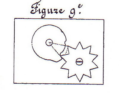
Perfecting this first mechanism We have seen that the results can only be communicated one single place to the left, that is, in the tens direction in the context of adding multiple-digit numbers. It was necessary to include the carries, as shown by the indicator, when adding the digits to the left, because of the absence of communication between the digits of a number. By adding an intermediate gear wheel to this mechanism, communication among multiple digits can be established, through placing below each dial a pinion which meshes with a similar pinion carrying a finger of twice the pinion diameter ; this finger is positioned so as to advance or turn back the dial pinion at the left by one tooth ; whenever passing from 9 to 0 or from 0 to 9, the [carry] indication affects the tens accordingly. The double length of the finger leaves the dial at the left free in such a way that motion can not be communicated from left to right, but only from right to left. Since this finger has a double length, it moves at double speed which could cause a two-tooth movement due to the momentum it acquires. Pawls or shutters have been established, which have two effects ; while on the one hand the pawl is lifted, on the other hand a point is lowered between two teeth ; if the impulse is too strong, one of the wheels encounters the point, which halts the wheel.
Signed in duplicate at Paris on the 28th of December 1849
Thomas
► Consult the original manuscript document in .pdf format (5 MB)
Table of diagrams :
* Transcribed from original patent manuscript by Valéry Monnier, France 2006. |
www.arithmometre.org
2007